Global OEM & Fabrication Partner for Port & Bulk Handling Equipment
全球港口及散货设备OEM制造合作伙伴
To reduce the vibration values of the 800t hoisting mechanism to acceptable standards, local reinforcement of the trolley bottom plate and drum supports is permitted. On the premise that the natural vibration frequencies of the trolley frame,
hoisting mechanism, and related components must not change, the vibration energy of the new 800 t gantry crane drum shall be suppressed. Therefore, this method has been formulated to significantly improve and ensure the machining accuracy,
assembly precision, static balance, and dynamic balance of the new drum (open to discussion and improvement). High-precision machining and assembly, combined with high-accuracy static and
dynamic balancing of large-diameter, long-length drums, is the key to reducing vibration in the hoisting mechanism. Do not assume that herringbone gears can necessarily solve vibration problems. The requirement is that the vibration velocity of
the drum and driving pinion (including bearing housings) of this size and weight must meet the standard (vibration velocity < 7.1 mm/s) at rotational speeds of 23 rpm and below under existing trolley installation conditions.
1. Key Technical Principles
A. Definition of Balance A rotating body is considered balanced when its center of
mass lies on the axis of rotation. However, absolute balance is only an ideal state; static unbalance or dynamic unbalance commonly exists. Static unbalance (Mr) is proportional to the radius of the eccentric mass. Static
balancing is most suitable for low-speed disc-shaped objects but not effective for solving rotational vibration of long shafts. Dynamic unbalance (Mr²) is proportional to the square of the eccentric radius. Dynamic balancing is most suitable for high-speed
discs and long shaft components.
B. Necessity of Dynamic Balancing Static and dynamic balance are independent
concepts and cannot replace each other. Good static balance does not guarantee good dynamic balance. For long drums, eccentric masses in different cross-sections can cause dynamic unbalance along the length direction (“decoupling” effect),
producing opposing force couples and torsional vibration. For cases with previous vibration exceedance, dynamic unbalance detection and elimination are mandatory. Due to the single-piece drum (net weight 29.3 t excluding
bull gear and brake disc), no suitable dynamic balancing machine is available. Determining dynamic unbalance for such a large drum remains a technical challenge.
C. Vibration Energy Vibration power (Mgh × n, SI units) is expressed in watts (W). For
example, 1 kg of dynamic unbalance produces approximately 8.3 W; a force couple produces approximately 16.5 W. Larger dynamic unbalance results in greater
vibration and noise.
D. Material Considerations The softening point of the steel is approximately 440°C.
Annealing can cause the drum to lose roundness under its own weight.
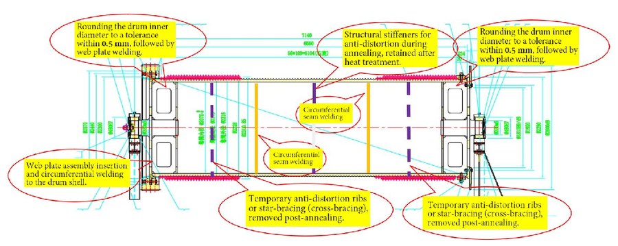
Figure 1
This standard applies to the manufacturing process control of the 800 t gantry crane (three-section ring-welded) hoisting drum.
2. Key Points for Drum Rolling and Forming
2.1 Material Preparation (August 1) Divide and cut three segments of 80 mm thick
Grade 355 steel plate (ultrasonically tested).
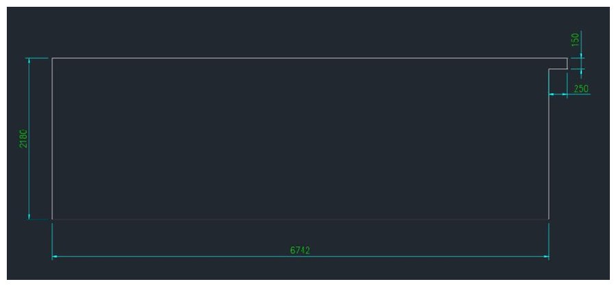
Figure 2
2.2 Cylinder Forming Form the cylinder on a large plate rolling machine. Cut off
excess material at longitudinal seams, preheat and pre-bend the plate ends, and roll to target inner diameter accuracy of Ø2070 ±1 mm. The three longitudinal welds shall
be staggered by 120°.
2.3 Groove Preparation and End Plate Welding Perform bevel chamfering, allow
machining allowance for rope groove surface after quenching, and machine inner ends for minimal eccentricity. Weld end plates and shafts (August 28).
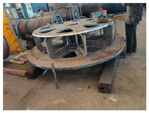
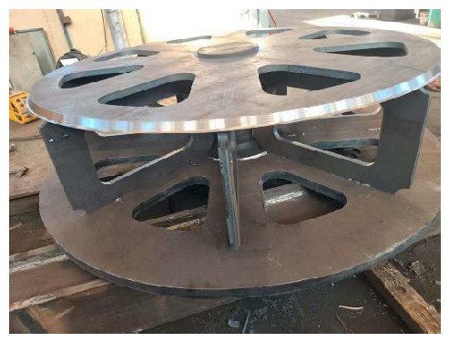
Figure 3 Figure 4
2.4 Sectional Alignment and Welding (August 30) Align drum sections on a lathe-rail
jig using 350 t hydraulic jacks for internal positioning and fixing to achieve full-length coaxiality within 0.5 mm. Apply low-deformation submerged arc welding with preheating (100–200°C) and post-weld heat or hydrogen elimination treatment.
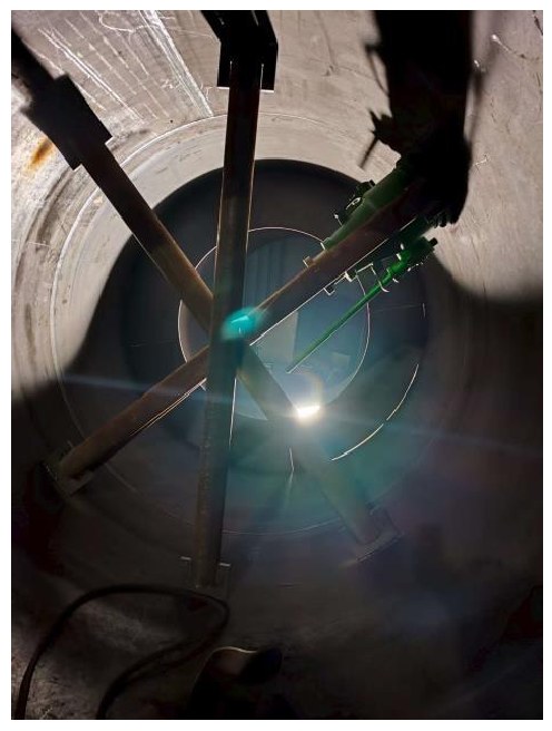
Figure 5
2.5 Non-Destructive Testing (September 7)
Perform magnetic particle or penetrant inspection on welds and near-surface areas.
2.6 Rough Machining and Internal Reinforcement Weld drum shafts and webs. Install
internal reinforcing ribs in the three drum sections to control annealing distortion.
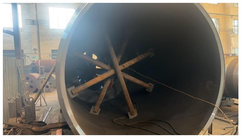
Figure 6
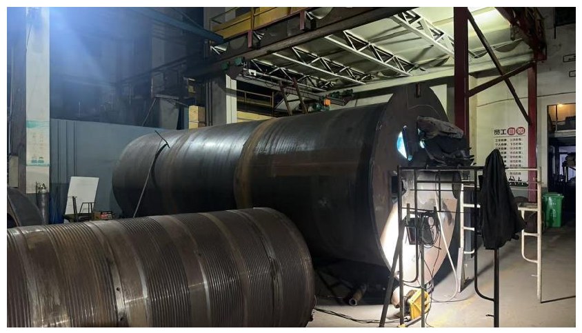
Figure 7
Note: Actual inner diameter is approximately 6 mm smaller than Ø2070. Jack-induced
roundness error is 0.5 mm.
3. Overall Annealing Heat Treatment (September 6)
Heat the drum slowly (≤80°C/h) to 580–610°C (max. 620°C), hold for more than 2 hours, then furnace cool to below 300°C followed by air cooling. Use multi-point external supports when placing horizontally in the furnace.
4. Machining and Balancing Procedure
4.1 Preliminary Static Balancing (September 18)
Perform preliminary static balancing before assembly of gears, brake discs, and
pressure plates.
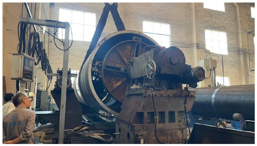
Figure 8
Associated Transmission Components (herringbone gear measures to be confirmed):
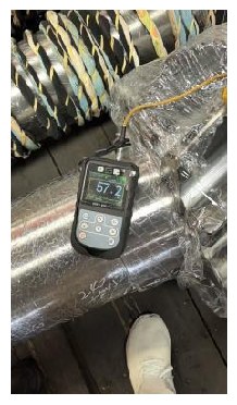
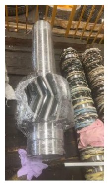
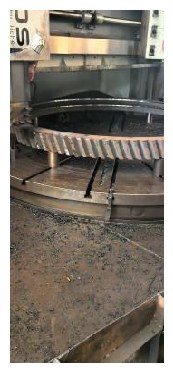
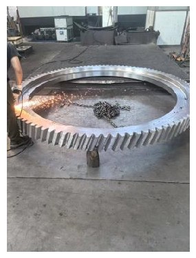
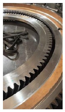
Figure 9 Figure 10 Figure 11 Figure 12 Figure 13
4.2–4.3 Rough Machining
Machine shafts and outer cylinder using the mutual datum principle. Record circumferential runout at 8 equal divisions every 500–600 mm along the drum length (see attached Table GW-S-QZ-W243-1) for segmental static balancing reference.
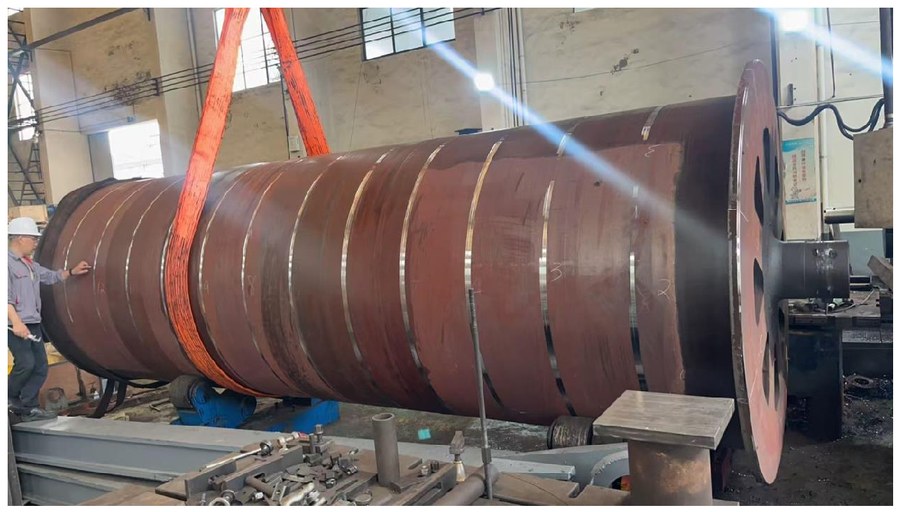
Figure 14
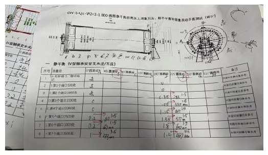
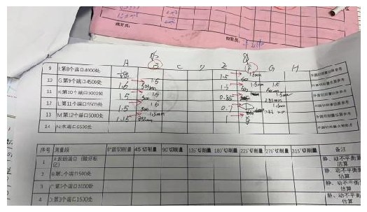
Figure 15 Figure 16
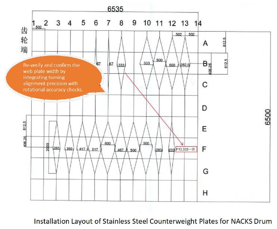
Figure 17
4.4 In-Process Adjustment Ensure full-length radial runout does not exceed 0.05 mm.
Adjust internal balance iron plates (quantity, size, and position) based on flange
measurements.
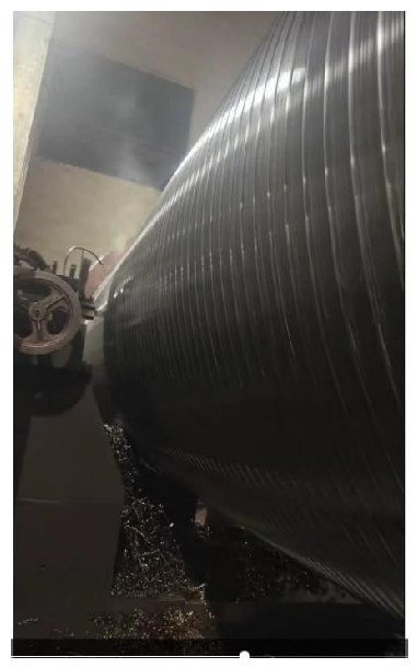
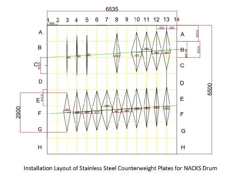
Figure 18 Figure 19
5. Rope Groove Processing
Machine rope grooves, followed by surface quenching (9 m/h). Verify hardness HB300 ±20 and perform magnetic particle inspection.
6. Final Static Balancing
After assembling all parts, perform overall static balancing on V-type support test stand. First symmetrically balance the wire rope press plates, then conduct overall
static balancing.
7. Dynamic Balancing Verification
Mount the complete drum assembly on the lathe for dynamic balancing test at 23 rpm. Vibration velocity shall not exceed the target value (4 mm/s).
8. Other Components
Perform static balancing on the pinion shaft, bearings, and coupling.
为降低 800t 起升机构的振动值至达标,允许对小车底板下局部、卷筒支承进行加强。在不改变小车架、起升机构及相关部件固有振动频率的前提下,抑制新 800t 门座起重机卷筒的振动能量。为此制定本方法,以显著提高并保证新卷筒的加工精度、装配精度、静平衡与动平衡(欢迎讨论改进)。
大直径、长筒体卷筒的高精度加工与装配,配合高精度的静、动平衡,是降低起升机构振动的关键。不要想当然地认为人字齿轮一定能解决振动问题。要求在现有小车安装条件下,该尺寸、重量的卷筒及传动小齿轮(含轴承座)在 23rpm 及以下转速时,振动速度须达标(振动速度 < 7.1mm/s)。
一、关键技术原理
A. 平衡的定义:当旋转体的质心位于旋转轴线上时即视为平衡。但绝对平衡只是理想状态,普遍存在静不平衡或动不平衡。静不平衡 (Mr) 与偏心质量半径成正比,静平衡最适用于低速盘类零件,但不能解决长轴的旋转振动。动不平衡 (Mr²) 与偏心半径的平方成正比,动平衡最适用于高速盘件和长轴类部件。
B. 动平衡的必要性:静平衡与动平衡是相互独立的概念,不能相互替代。静平衡良好并不能保证动平衡良好。对于长卷筒,不同截面上的偏心质量会沿长度方向产生动不平衡(“解耦”效应),形成方向相反的力偶和扭转振动。对以往出现过振动超标的情况,必须进行动不平衡的检测与消除。由于卷筒为整体单件(净重 29.3t,不含大齿圈和制动盘),缺乏合适的动平衡机,确定如此大型卷筒的动不平衡仍是技术难题。
C. 振动能量:振动功率 (Mgh×n,SI 单位) 以瓦 (W) 表示。例如 1kg 的动不平衡约产生 8.3W,一个力偶约产生 16.5W。动不平衡越大,振动和噪声越大。
D. 材料考虑:钢材软化点约 440°C。退火可能使卷筒在自重作用下失圆。
图 1
本标准适用于 800t 门座起重机(三段环焊)起升卷筒的制造过程控制。
二、卷筒卷制成型要点
2.1 备料(8 月 1 日):分料、切割三段 80mm 厚 355 级钢板(经超声波探伤)。
图 2
2.2 筒体成型:在大型卷板机上卷制筒体。切除纵缝多余材料,对板端预热预弯,卷制至目标内径精度 Ø2070 ±1mm。三条纵焊缝应错开 120°。
2.3 坡口准备与端板焊接:进行坡口倒角,淬火后绳槽面留加工余量,加工内端以使偏心最小。焊接端板与轴(8 月 28 日)。
图 3 图 4
2.4 分段对中与焊接(8 月 30 日):在车床导轨工装上用 350t 液压千斤顶进行内部定位与固定,使全长同轴度在 0.5mm 以内。采用低变形埋弧焊并预热 (100–200°C),焊后进行消氢或热处理。
图 5
2.5 无损检测(9 月 7 日):对焊缝及近表面区域进行磁粉或渗透检测。
2.6 粗加工与内部加强:焊接卷筒轴与腹板。在三段卷筒内安装内部加强筋,以控制退火变形。
图 6
图 7
注:实际内径比 Ø2070 约小 6mm。千斤顶引起的圆度误差为 0.5mm。
三、整体退火热处理(9 月 6 日)
缓慢加热卷筒 (≤80°C/h) 至 580–610°C(最高 620°C),保温 2 小时以上,随炉冷却至 300°C 以下后空冷。水平入炉时采用多点外部支承。
四、加工与平衡工序
4.1 初步静平衡(9 月 18 日):在装配齿轮、制动盘和压板之前进行初步静平衡。
图 8
相关传动部件(人字齿轮措施待确认):
图 9 图 10 图 11 图 12 图 13
4.2–4.3 粗加工:按互为基准原则加工轴与外筒。沿卷筒长度每 500–600mm 在 8 等分处记录圆周跳动(见附表 GW-S-QZ-W243-1),作为分段静平衡参考。
图 14
图 15 图 16
图 17
4.4 过程调整:确保全长径向跳动不超过 0.05mm。根据法兰测量调整内部平衡铁板(数量、尺寸和位置)。
图 18 图 19
五、绳槽加工
加工绳槽,随后进行表面淬火 (9m/h)。验证硬度 HB300 ±20 并进行磁粉检测。
六、最终静平衡
全部零件装配后,在 V 型支承试验台上进行整体静平衡。先对称平衡钢丝绳压板,再进行整体静平衡。
七、动平衡验证
将整体卷筒组件装在车床上进行 23rpm 动平衡试验。振动速度不得超过目标值 (4mm/s)。
八、其他部件
对小齿轮轴、轴承和联轴器进行静平衡。